Analog Sensors Reading with Raspberry Pi and Zabbix Supervisor
2014-01-13
This article is based in this very good one
I added some comments, examples, circuits and Zabbix configuration.
The main goal is having a common interface to read analog values and generate graphs, alarms, actions etc. with Zabbix.
Analog Sensors Reading with Raspberry Pi as Interface
The Raspberry Pi has no built in analogue inputs which means it is a bit of a pain to use many of the available sensors. We need a A/D interface easy to configure in the RPi and the MCP3008 is the answer.
The MCP3008 is a 10bit 8-channel Analogue-to-digital converter (ADC). It is cheap, easy to connect and doesn’t require any additional components. It uses the SPI bus protocol which is supported by the Pi’s GPIO header.
This article explains how to use an MCP3008 device to provide 8 analogue inputs which you can use with a range of sensors. In the example circuit below I use a MCP3008 to read a light sensor and control/supervise the light inside Zabbix.
The hardware:
- Raspberry Pi
- MCP3008 8 channel ADC
- Light dependent resistor (LDR)
- 10 Kohm resistor
- Breadboard
- Some wiring
SPI Bus
The MCP3008 read the analog value and give a 10 bits number that is transmitted by the SPI Bus. 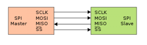
The Serial Peripheral Interface bus or SPI bus is a synchronous serial data link standard, that operates in full duplex mode.
Devices communicate in master/slave mode where the master device initiates the data frame. Multiple slave devices are allowed with individual slave select lines.
Sometimes SPI is called a four-wire serial bus, contrasting with three-, two-, and one-wire serial buses. SPI is often referred to as SSI (Synchronous Serial Interface).
To enable hardware SPI on the RPi we need to make a modification to one of the system files:
sudo nano /etc/modprobe.d/raspi-blacklist.conf
Add a ‘#’ character in front of the line spi-bcm2708. Use CTRL-X, then Y, then Return to save the file and exit. Reboot using the following :
sudo reboot
To check the change has worked run the following command :
lsmod
You should see “spi_bcm2708″ listed in the output.
Install Python SPI Wrapper
In this project we are going to use Python and In order to read data from the SPI bus in Python we can install a library called ‘py-spidev’. To install it we first need to install ‘python-dev’ :
sudo apt-get install python-dev
Then to finish we can download ‘py-spidev’ and compile it ready for use :
mkdir py-spidev
cd py-spidev
wget https://raw.github.com/doceme/py-spidev/master/setup.py
wget https://raw.github.com/doceme/py-spidev/master/spidev\_module.c
sudo python setup.py install
Circuit
The following list shows how the MCP3008 can be connected. It requires 4 GPIO pins on the Pi P1 Header.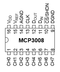
| MCP3008 | RPi |
|---|---|
| VDD | 3.3V |
| VREF | 3.3V |
| AGND | GROUND |
| CLK | GPIO11 (P1-23) |
| DOUT | GPIO9 (P1-21) |
| DIN | GPIO10 (P1-19) |
| CS | GPIO8 (P1-24) |
| DGND | GROUND |
The CH0-CH7 pins are the 8 analogue inputs.
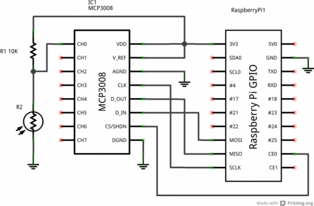
Next we can see the schematic of the circuit:
Here is the breadboard circuit :
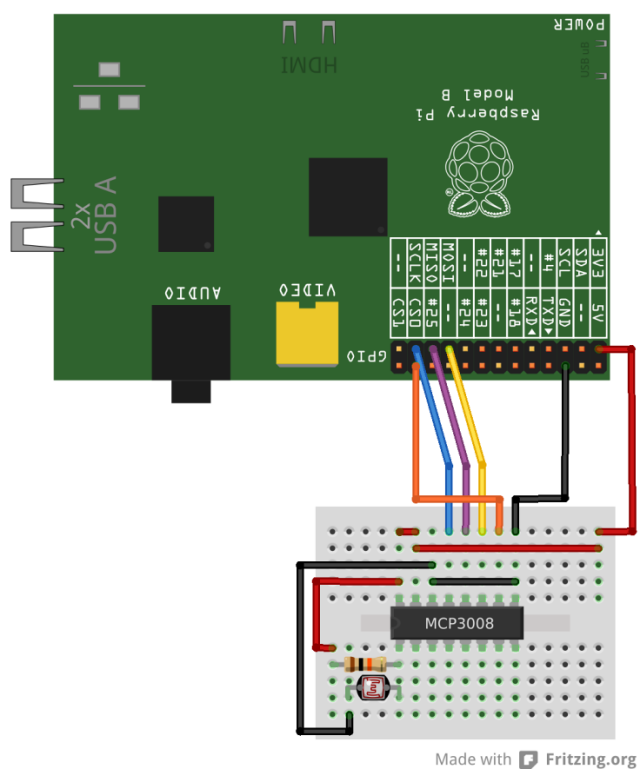
It uses CH0 for the light sensor. The other 7 inputs are spare.
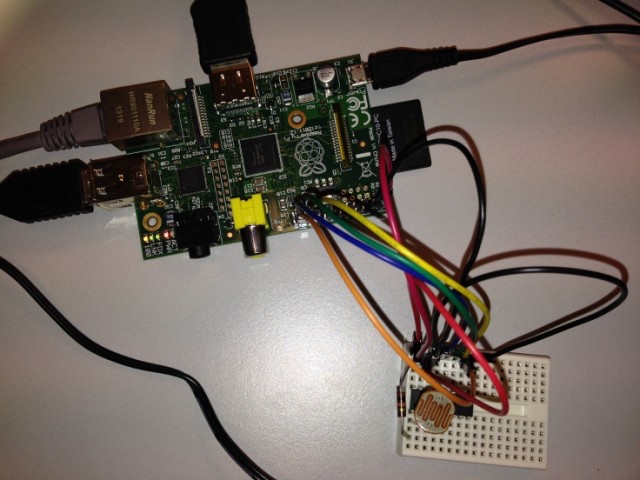
Here is a photo of my test circuit on a small piece of breadboard:
Light Dependent Resistor
I chose a LDR EG & G Vactec, VT43, CdS, 8 Ω to 300 KΩ. Under normal lighting its resistance is approximately 10Kohm while in the dark this increases to over 2Mohm.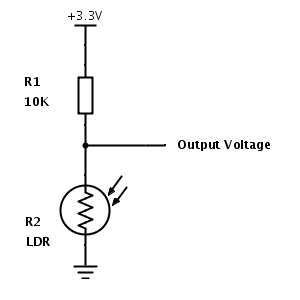
When there is lots of light the LDR has a low resistance resulting in the output voltage dropping towards 0V.
When it is dark the LDR resistance increases resulting in the output voltage increasing towards 3.3V. In this project has been used a LDR but whatever device changing his resistance depending of some phenomenon can be used and wired in the IC to be controlled.
Reading The Data
The ADC is 10bit so it can report a range of numbers from 0 to 1023 (2 to the power of 10). A reading of 0 means the input is 0V and a reading of 1023 means the input is 3.3V. Our 0-3.3V range would equate to a 0-10000 Lux range.
To read the data I used this Python script get_light.py:
#!/usr/bin/python

#!/usr/bin/python

import spidev
import time
import os

# Open SPI bus
spi = spidev.SpiDev()
spi.open(0,0)

# Function to read SPI data from MCP3008 chip
# Channel must be an integer 0-7

def ReadChannel(channel):
adc = spi.xfer2([1,(8+channel)<<4,0])
data = ((adc[1]&3) << 8) + adc[2]
return data

# Function to convert data to voltage level,
# rounded to specified number of decimal places.

def ConvertVolts(data,places):
volts = (data * 3.3) / 1023
volts = round(volts,places)
return volts

# Define sensor channels
light_channel = 0

# Define delay between readings
delay = 1

while True:
# Read the light sensor data
light_level = 1024 – ReadChannel(light_channel)
light_volts = ConvertVolts(light_level,2)

# Print out results
print “——————————————–”
print(“Light: {} ({}V)”.format(light_level,light_volts))

# Wait before repeating loop
time.sleep(delay)
The output with normal light is:
pi@pi-access-lab ~ $ ./get_light.py
——————————————–
Light: 904 (2.92V)
——————————————–
Light: 895 (2.89V)
——————————————–
Light: 903 (2.91V)
——————————————–
Light: 895 (2.89V)
——————————————–
Light: 904 (2.92V)
——————————————–
Light: 906 (2.92V)
——————————————–
Light: 896 (2.89V)
——————————————–
Light: 887 (2.86V)
——————————————–
Light: 894 (2.88V)
——————————————–
Light: 906 (2.92V)
——————————————–
ZABBIX Integration
Zabbix Agent
The Zabbix Agent must be installed in the RPi in order to receive the requests from the server and send the value read. Install the agent with:
sudo apt-get update && sudo apt-get install zabbix-agent
The script written in Python has to be modified a bit. we want to have 100% light for the maximum light and 0% for the minimum.
SSM Server request light to RPi → Zabbix Agent send only the percent as a number.
Here is the python code modified:
#!/usr/bin/python

import spidev
import time
import os

# Open SPI bus
spi = spidev.SpiDev()
spi.open(0,0)

# Function to read SPI data from MCP3008 chip
# Channel must be an integer 0-7
def ReadChannel(channel):
adc = spi.xfer2([1,(8+channel)<<4,0])
data = ((adc[1]&3) << 8) + adc[2]
return data

# Function to convert data to voltage level,
# rounded to specified number of decimal places.
def ConvertVolts(data,places):
volts = (data * 3.3) / 1023
volts = round(volts,places)
return volts

# Define sensor channels
light_channel = 0

# Read the light sensor data
light_level = (1024 – ReadChannel(light_channel)) / 10.24
light_volts = ConvertVolts(light_level,2)

# Print out results
print(“{:.3}”.format(light_level))
The output with normal light is:
[code language=”bash”]
pi@pi-access-lab ~ $ ./ssm_get.py
88.4
The zabbix_agent must be configured as usual with the Zabbix Server server etc, and add the command lines at the end of the configuration file. When the server request light the agent must know what to do. That is done editing the file:
/etc/zabbix/zabbix\_agentd.conf
and adding:
### Option: UserParameter

# User-defined parameter to monitor. There can be several user-defined parameters.
# Format: UserParameter=,
# Note that shell command must not return empty string or EOL only.
# See ‘zabbix_agentd’ directory for examples.
#
# Mandatory: no
# Default:

UserParameter=light,sudo /home/pi/ssm_get.py
Another important hack is that the user running the zabbix_agent (in my case zabbix) must have the rights to execute the command as root since we are accessing to the SPI port of the RPi. If we want to avoid writing the passwords in the scripts we can authorise the user zabbix in the sudoers file only for the command or in my case more general:
/etc/sudoers
# See sudoers(5) for more information on “#include” directives:
#includedir /etc/sudoers.d
pi ALL=(ALL) NOPASSWD: ALL
zabbix ALL=(ALL) NOPASSWD: ALL
Zabbix Server
To check the installation before adding the host and checks in the server we can run in the Zabbix Server:
[root@server ~]# zabbix_get -s pi-access-lab -k light
87.5
If that works and return the value, we can add the RPi in the Zabbix Server and create an item called light or whatever we want and associate an external check:
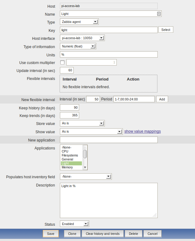
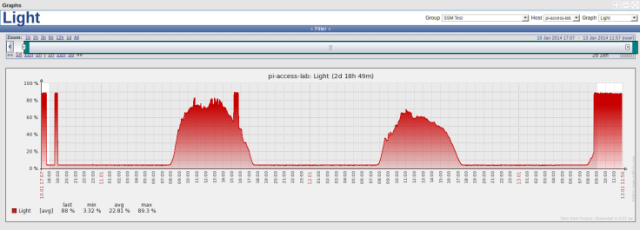
We can create screens for the data, graphs or whatever we need. Refer to the Zabbix documentation to do it. The result after 2 or 3 days getting data in my desk is:
11 Comments
Martin on 07/05/2014 at 15:15
Is it possible to connect more than one MCP3008 + LDR to the SPI bus with this setup? And is it possible to address this SPI via USB with standaard USB-SPI converters like ‘Bus Pirate’ ?
Tono on 07/05/2014 at 15:41
Hi Martin,
Well, reading http://en.wikipedia.org/wiki/Serial_Peripheral_Interface_Bus I would say yes, you can, but look not too simple… What I would do is getting a chip with more inputs if you need more than 8 converters. For the USB-SPI converters, honestly, I don’t know. I never used any of them.
Regards.
Andres on 04/11/2014 at 14:55
Good information, thank’s 😉
DanielCamargo on 13/02/2015 at 01:19
Hello Tono, can I receive more than one parameter using “UserParameter” in the agentd.conf with the same python script. I’ld like to measure temperature, humidty, pressure and light. Can you help me with this? Thanks!
Tono on 13/02/2015 at 09:59
Hi Daniel, I don’t know how is done your python script but my advice is that you do one python script for each parameter (temp, light, etc.) or a python script that take a command line argument. You have several and very good examples to do that here: http://www.tutorialspoint.com/python/python_command_line_arguments.htm.
Now, imagine you do a script that take the commands of: temp and light… The most important is that when you run in the command line of the RPi, the script return “something” exemple:
script.py temp
23.2

script.py light
350
The script should return the temperature without anything else! Verify that doesn’t return the carrier return or other characters that could have problems with the Zabbix agent. (I had problems in the past)
Now, in the zabbix_agentd.conf you have to put 2 lines like this: UserParameter=temp,script.py temp UserParameter=light,script.py light
Later in the Zabbix interface create 2 items with the names: light and temp and is done!
An example from my system that is working: In the Raspberry Pi when I run: “cat /sys/class/thermal/thermal_zone0/temp” that returns the CPU temperature. For taking this value inside Zabbix, I write in the zabbix_agentd.conf:
UserParameter=cpu.temp,cat /sys/class/thermal/thermal_zone0/temp
In Zabbix, I create a Item in the Rasperry Host like this:
Name: CPU Temperature
Type: Zabbix agent
Key: cpu.temp
Host interface: Raspberry Host
Type of information: Numeric (float)
Units: Degrees
Use custom multiplier: 0.001
Hope that helps.
DanielCamargo on 20/02/2015 at 22:16
Hello Tono,
This is the answer that is closer to me resolve the issue. I will test and notice here. Thank you for your help.
DanielCamargo on 28/02/2015 at 18:48
Hi Tono,
I managed to send multiple data using zabbix-api for Python using JSON format. The module I used was the zbxsend (github.com/pistolero/zbxsend). Thank you for your help! It was essential for my research project.
Tono on 28/02/2015 at 18:50
Nice to know that helped.
Chandan Bathula on 22/11/2016 at 14:11
Hello Tono
I am a student and i am new to Python and as well as Raspberry pi 3. I have a project where i have to record the data from the temperature sensor using raspberry pi 3 and mcp3008. I have to transfer these values to another pc via wifi and generate graphs of these values. Could you give me some inputs so that i could go forward with my project. Thanking you in advance.
Daniel dos Santos Silva on 05/05/2017 at 13:44
Hi Tono… Can you reupload the broken link images? Thanks.
Tono Riesco on 05/05/2017 at 14:37
Hi Daniel,
Thank you for telling me. I did it.
Regards.